High-Temperature, Vacuum Furnace Electrode
Project Statement
Design and development of an electrode assembly to enable power transfer to a graphite resistive heating element within a bespoke high-temperature vacuum furnace. The electrodes were required to withstand a hot-end temperature exceeding 2000 °C while maintaining an external temperature no greater than 150 °C, as limited by an off-the-shelf copper KF vacuum electrical pass-through. Electrical performance requirements specified a maximum current of 150 amps per electrode.
The assembly was also required to tolerate a minimum of 30 thermal cycles to approximately 2000 °C, with high-temperature dwell times of up to 4 hours per cycle. Project delivery constraints were stringent, with approximately one week allocated for design and one week for prototyping and fabrication.
Ideation and Technical Challenges
The extreme temperature requirements placed primary emphasis on material selection. Hot-end components required stability above 2000 °C, along with chemical inertness within a high-temperature reducing environment. Simultaneously, the electrode assembly needed to maintain high electrical conductivity while minimizing thermal conductivity along the axial direction toward the reactor exterior. This was necessary to limit heat loss from the insulated system and to ensure that the copper pass-through remained below its maximum allowable operating temperature.
Only a limited number of materials are capable of withstanding temperatures above 2000 °C without melting, sublimating, or undergoing catastrophic embrittlement. Material research identified graphite, tungsten, and molybdenum as viable candidates. Cost and material availability were significant considerations due to the requirement for production of at least 16 units. Additionally, the design required serviceability and straightforward component replacement to support long-term operation.
Process and Technical Challenges
The design process began with consolidation of key material properties, including coefficients of thermal expansion and thermal conductivity, alongside geometric constraints imposed by the reaction crucible heating volume within the reactor.
A one-dimensional thermal model was developed, representing each electrode as a series of discrete thermal resistances. Primary design variables within the model included material diameters, thermal conductivities, and electrode section lengths. This modeling approach enabled rapid iteration and optimization within defined constraints, with the off-the-shelf KF copper electrical pass-through serving as the dominant boundary condition.
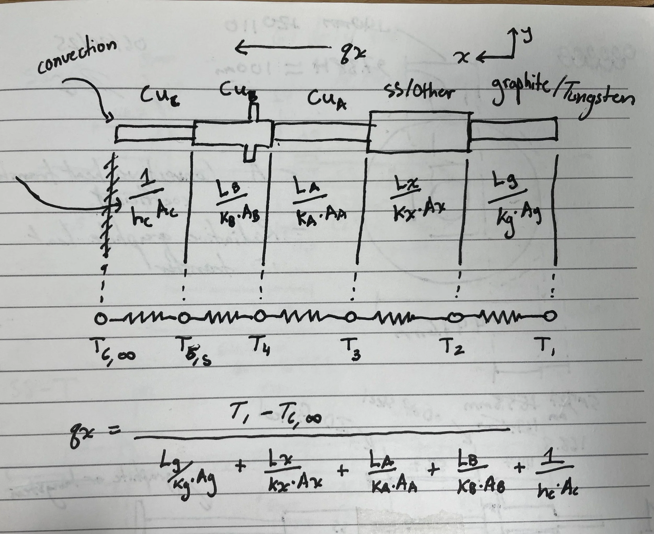
Fig. 1: 1D Thermal Model
qₓ (Fig. 1) represented the heat flux through the system. A script was produced to allow faster iteration and rapid testing of various section lengths and material selections. In addition, the script generated predicted temperatures at each stage of the electrode. Though predictive, the model was intended to be refined using empirical data collected during testing.
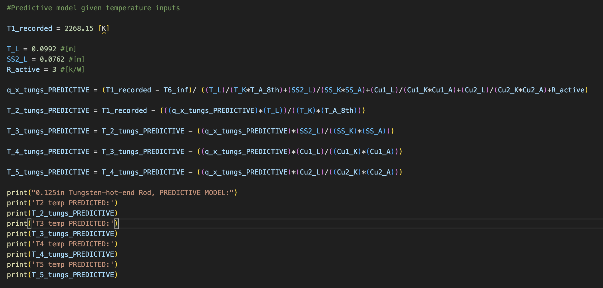
Fig. 2: 1D Predictive Thermal Model
The design was narrowed to two initial configurations:
Configuration 1: Graphite hot end
Configuration 2: Tungsten hot end
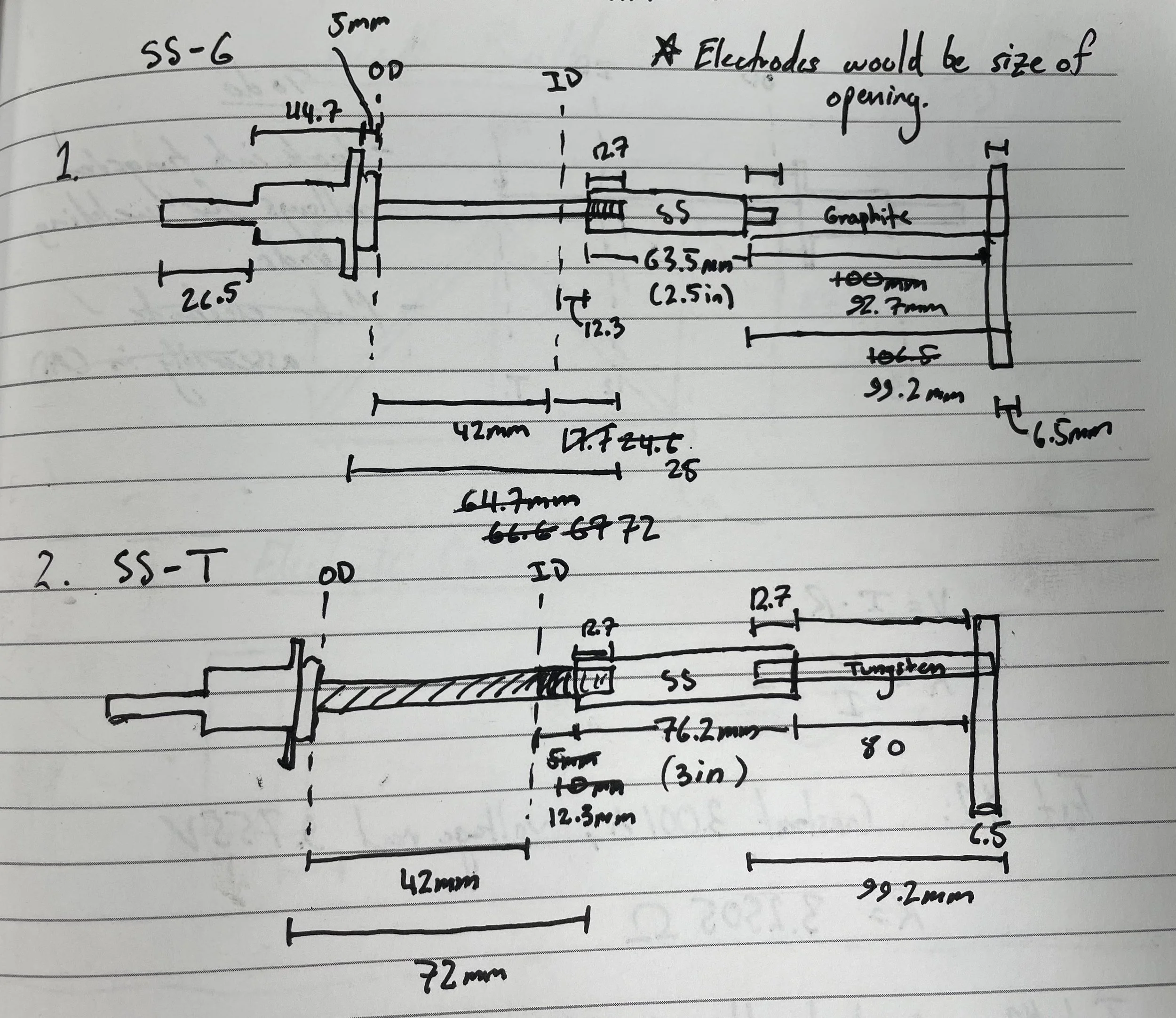
Fig. 3: Design Configurations 1 and 2
Ultimately, configuration 2 with a tungsten hot-end was selected. Graphite’s higher thermal conductivity would have required a smaller cross-sectional area to maintain a sufficient thermal resistance, which would have been structurally unstable. Additionally, while graphite is inherently brittle, it further embrittles at elevated temperatures, which could have been problematic during sample loading into the reactor and for achieving the minimum of 30 heating cycles.
Next, heat transfer calculations were conducted to assess whether natural heat dissipation at the external end of the copper KF electrical pass-through would be sufficient to limit a maximum temperature of 150 °C. If heat transfer was sufficient, there would be no need for additional cooling via a heat sink and forced air cooling.
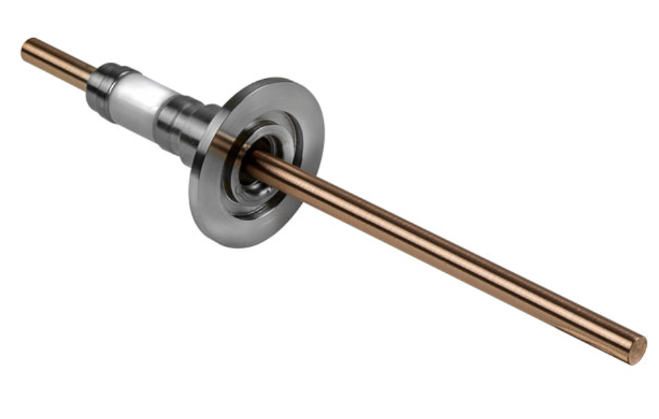
Fig. 4: Kf Copper Vacuum Pass-through, Heat Dissipation External End (See Upper Left)
Four steps were required for these calculations:
Calculation of the convective heat transfer coefficient, including determination of the Rayleigh number and Nusselt number, which were then used to solve for the convective heat transfer coefficient (h).
Use of (h) to determine the convective heat transfer rate.
Determination of the radiative heat transfer rate.
Calculation of total heat transfer through the system.
The calculated total heat transfer rate of <1 W (0.13169 W) indicated that additional heat dissipation would be required, via a heat sink and active cooling. A heat sink was selected based on local availability and cost. By adding forced cooling, the temperature gradient within the system would grow steeper, and the system would be much more effective at dissipating heat.
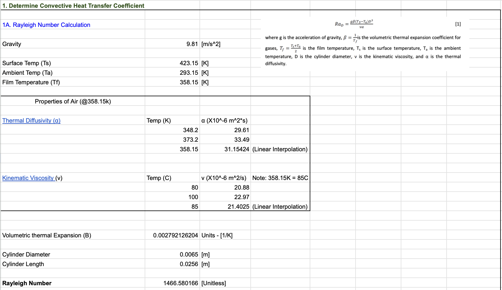
Fig. 4: Step 1A, Calculation Rayleigh Number
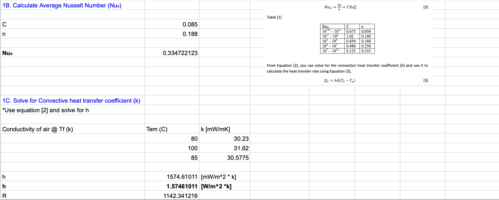
Fig. 5: Steps 1B & 1C, Solve for Convective Heat Transfer Coefficient (h)
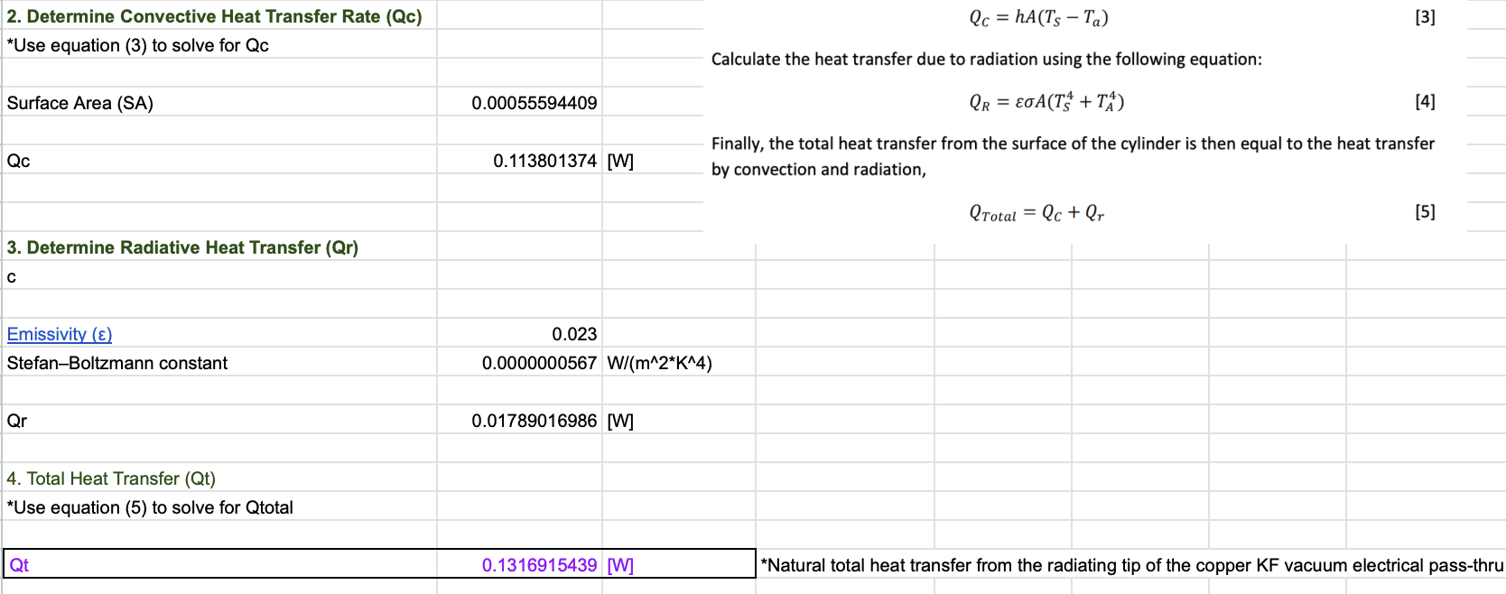
Fig. 5: Steps 2, 3 & 4, Solve for Total Heat Transfer (Qt)
In summary, the electrode was designed to maximize axial thermal resistance and minimize conductive heat loss out of the heating region, while maintaining a large temperature gradient between the hot and cold ends.
The total heat transfer calculations showed that natural convection at the external end of the copper pass-through was insufficient to reject heat, which would lead to elevated steady-state temperatures.
To address this, a heat sink and forced air cooling were introduced to increase heat dissipation at the boundary. While this increased the overall heat flux through the system, it lowered the cold-end temperature and ensured stable operation within component limits.
Solution: Final Design
The final design aligned strongly with Configuration 2, described above. A simple 3D-printed bracket was modeled to position a fan in close proximity to the heat sink.
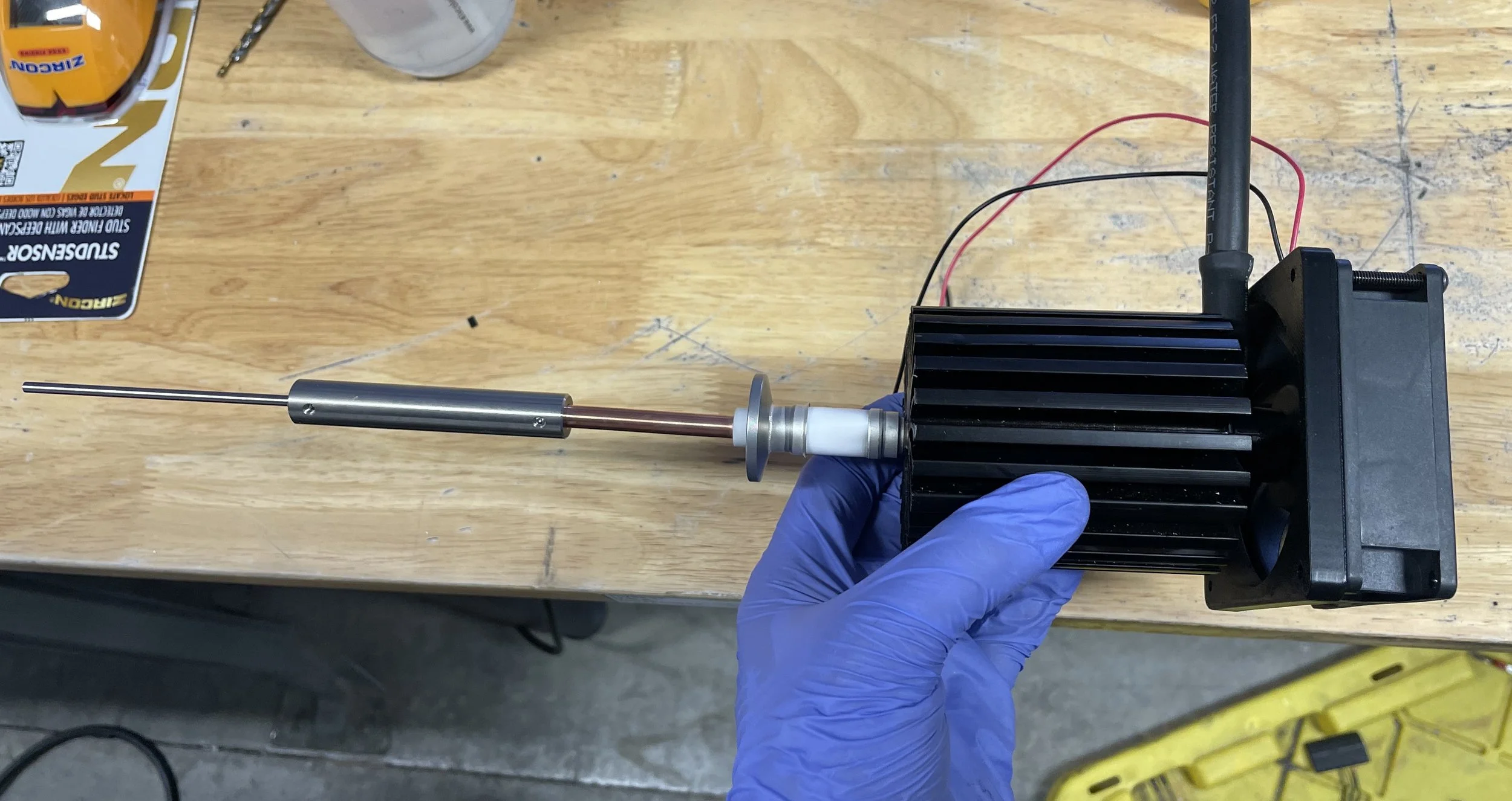
Fig. 7 Assembly of the Final Electrode
Below is a model of the full electrode assembly.
In partnership with a team member, a custom graphite geometry was developed to function as the resistive heating element between the two custom electrodes. DC power was supplied to the system with a maximum input power of 5 kW.
Design Validation
The electrodes were tested to their maximum operating temperature of 2000 °C. A pyrometer was used to determine the exact hot-end temperature (T1 in the 1D model), and a thermocouple was installed on the exterior copper section of the electrode pass-through (T5,s in the 1D model). Temperature data from these two points was used to further refine the model, improving understanding of intermediate temperatures and system heat flux.
With forced air cooling and a T1 temperature of 1995 °C, the maximum steady state temperature at T5,s never surpassed 70 °C during the 4-hour dwell time. The electrodes withstood more than 30 heating cycles, requiring refurbishment only after an unrelated issue with the alumina insulator, surrounding the electrode, prompted a system overhaul.
The design objectives were achieved, and the final product surpassed both expectations and requirements.